Android Bluetooth RGB Led
App In Action
Download the App
Bill of Materials
- 1 x Arduino with USB Cord
- 1 x RGB LED
- 1 x Bluetooth Module HC-05
- 13 x Jumper Wires 10
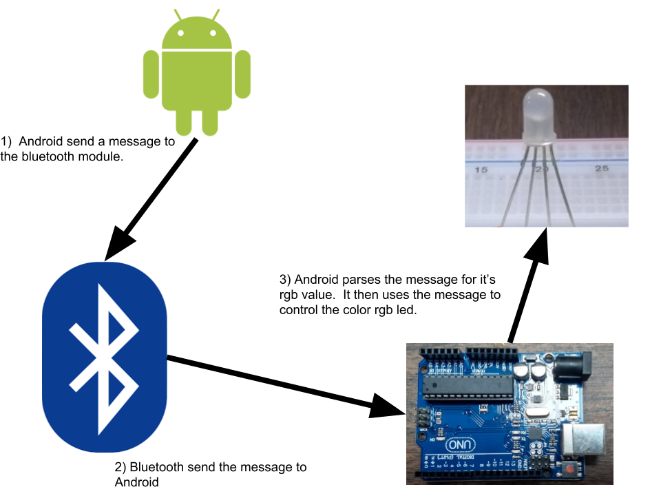
How it works?
The Android must be paired with the Arduino before using the app. This can be done in the settings.
1) Android will send a message to the Arduino that looks like this 30-0-50|. Each number represent a color. 30 = red, 0 = green, and 50 = 0 blue. The “|” is used to tell the Arduino to stop reading data.
2) Once this message is received by the Bluetooth device, it is passed to the Arduino.
3) The Arduino will parse the message and use it to control the rgb leds.
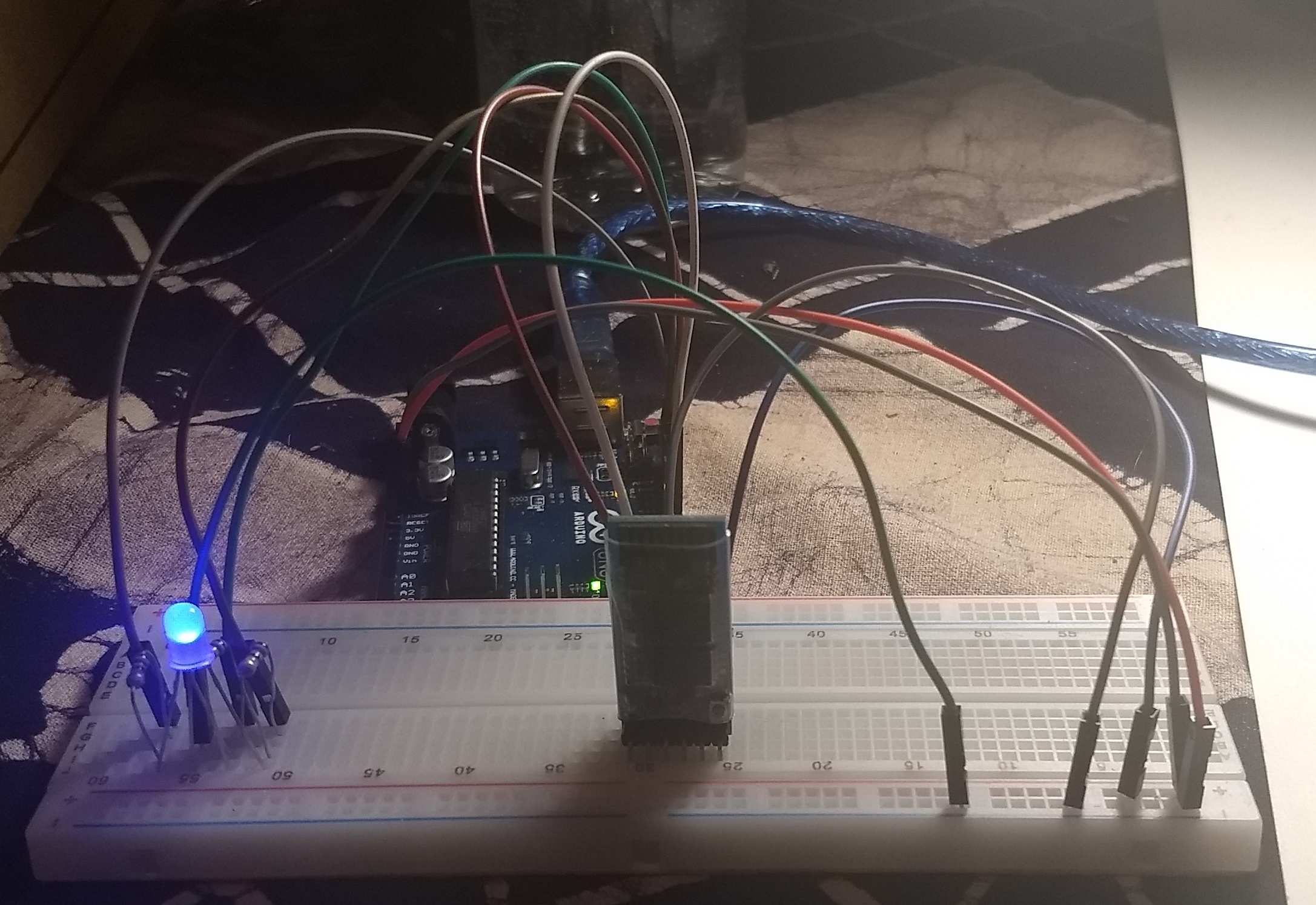
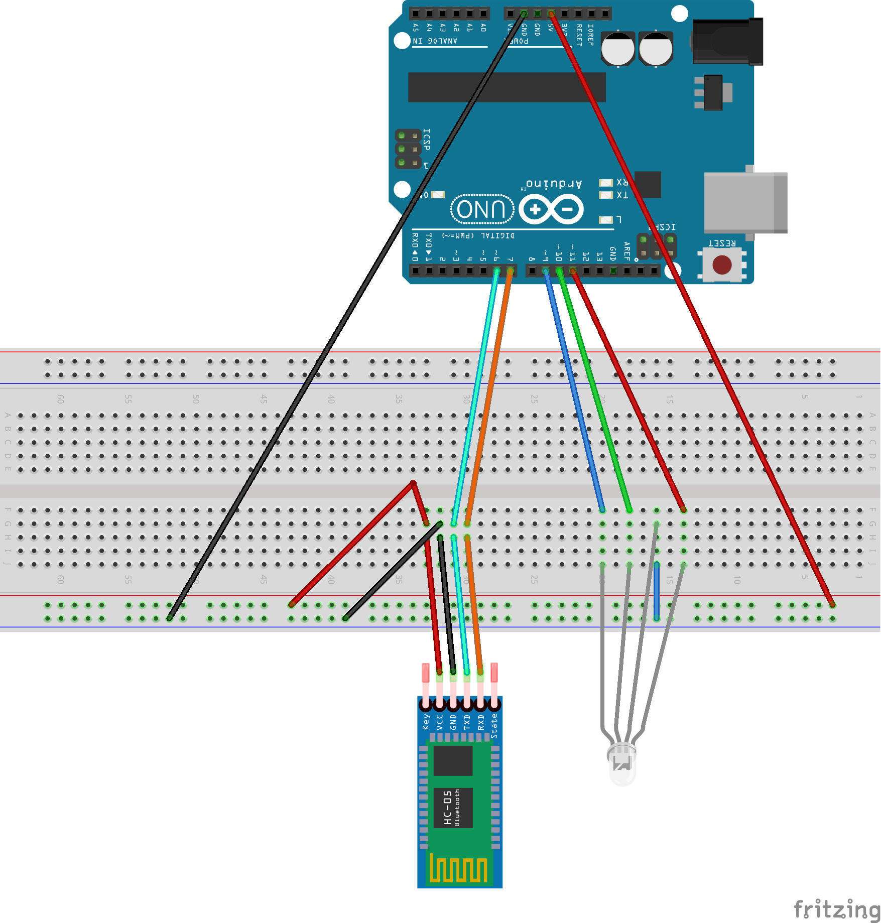
Circuit
When controlling rgb leds you must either use an analog pin or pins with the ~ next to them. These pins can do pulse with modulation (PWM).
Arduino Code
#include <SoftwareSerial.h>

SoftwareSerial blueToothSerial(6, 7);

String getParseValue(String data, char separator, int index) {
	int found = 0;	int strIndex[] = {0, -1};
	int maxIndex = data.length()-1;
	for(int i=0; i<=maxIndex && found<=index; i++){
	    if(data.charAt(i)==separator || i==maxIndex){
	        found++;
	        strIndex[0] = strIndex[1]+1;
	        strIndex[1] = (i == maxIndex) ? i+1 : i;
	    }
	}
	return found > index ? data.substring(strIndex[0], strIndex[1]) : "";
 }

void setup()
{
  blueToothSerial.begin(9600);
  blueToothSerial.write("AT+NAMErgb_led");
  blueToothSerial.write("AT+PIN4444");
  blueToothSerial.write("AT+BAUD4");
  delay(1000);
}


void loop()
{
  if (blueToothSerial.available()) {
    String bt_string = blueToothSerial.readStringUntil('|');
    int red = getParseValue(bt_string, '-', 0).toInt();
    int green = getParseValue(bt_string, '-', 1).toInt();
    int blue = getParseValue(bt_string, '-', 2).toInt();
    analogWrite(11, red);
    analogWrite(10, green);
    analogWrite(9, blue);
  }
}
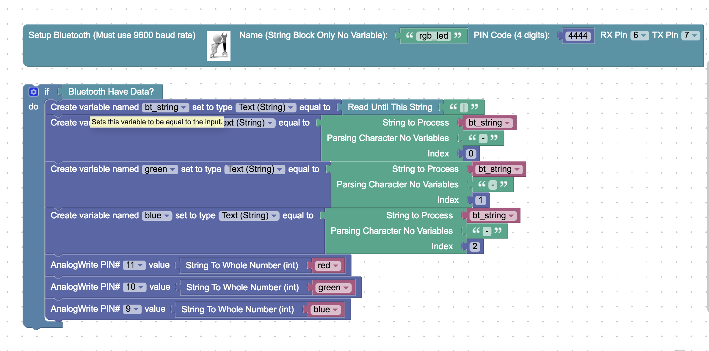
Arduino Blockly IDE Version