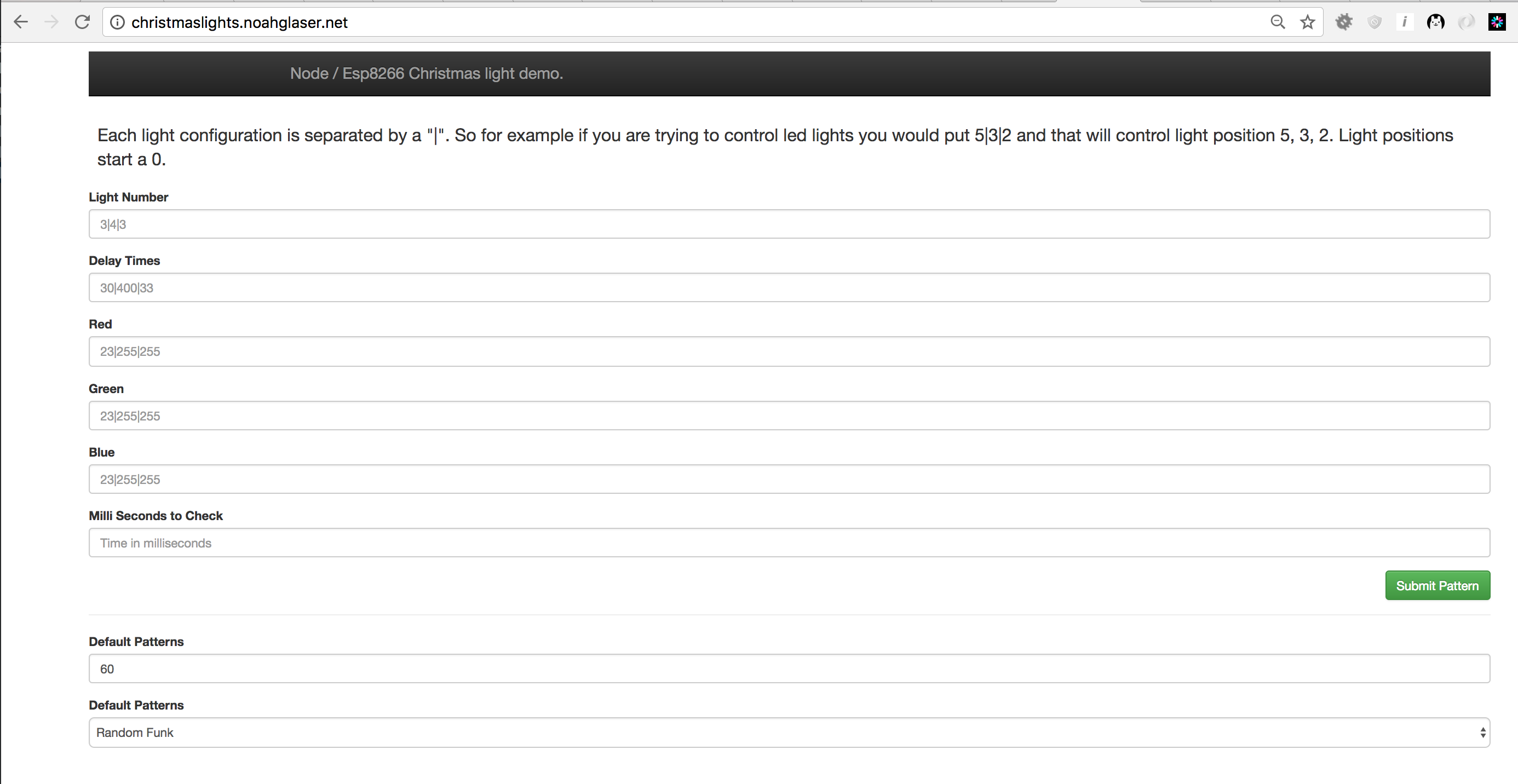
#include <Adafruit_NeoPixel.h>
#include <ESP8266WiFi.h>
#include <WiFiClient.h>
#include <ArduinoJson.h>

#ifdef __AVR__
  #include <avr/power.h>
#endif

/**
 * The number lights in your led strip
 */
#define NUMPIXELS      30

/**
 * The default time before request another pattern.  It's in milliseconds so it would be 10 seconds
 */
int intervalToCheckTime = 10000;

/**
 *  The time in the future to check the web for a new pattern.  We set it to zero, it will be set correctly in the web request
 */
int checkTimeInNumberOfSeconds = 0;

// When we setup the NeoPixel library, we tell it how many pixels, and which pin to use to send signals.
// Note that for older NeoPixel strips you might need to change the third parameter--see the strandtest
// example for more information on possible values.
Adafruit_NeoPixel pixels = Adafruit_NeoPixel(NUMPIXELS, D6, NEO_GRB + NEO_KHZ800);

WiFiClient client;

/**
 *  WIFI STUFF
 */
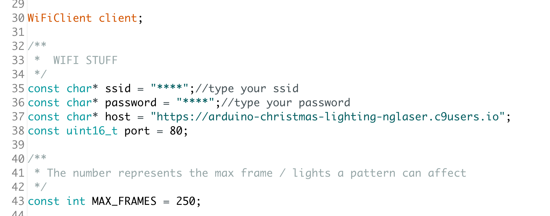
const char* ssid = "****";//type your ssid
const char* password = "****";//type your password
const char* host = "****"; // type in your cloud 9 url.
const uint16_t port = 80;

/**
 * The number represents the max frame / lights a pattern can affect
 */
const int MAX_FRAMES = 250;

/**
 * This represents a frame.
 */
struct RGB_LIGHT {
  int red;
  int green;
  int blue;
  int lightPosition;
  int delayTime;
  /**
   * If skip is true we break
   */
  boolean skip;
};

/**
 * The pattern / frames used to turn on and off the lights
 */
RGB_LIGHT lights[MAX_FRAMES];

void setup() {
  // This is for Trinket 5V 16MHz, you can remove these three lines if you are not using a Trinket
#if defined (__AVR_ATtiny85__)
  if (F_CPU == 16000000) clock_prescale_set(clock_div_1);
#endif
  // End of trinket special code

  pixels.begin(); // This initializes the NeoPixel library.
  Serial.begin(115200);
  delay(10);

  // We start by connecting to a WiFi network

  Serial.println();
  Serial.println();
  Serial.print("Connecting to ");
  Serial.println(ssid);

  /* Explicitly set the ESP8266 to be a WiFi-client, otherwise, it by default,
     would try to act as both a client and an access-point and could cause
     network-issues with your other WiFi-devices on your WiFi-network. */
  WiFi.mode(WIFI_STA);
  WiFi.begin(ssid, password);

  while (WiFi.status() != WL_CONNECTED) {
    delay(500);
    Serial.print(".");
  }

  Serial.println("");
  Serial.println("WiFi connected");
  Serial.println("IP address: ");
  Serial.println(WiFi.localIP());

  clearLights();
  webRequest();
  checkTimeInNumberOfSeconds = millis() + intervalToCheckTime;

}

void loop() {

  if (checkTimeInNumberOfSeconds > millis()) {
     for(int frameNumbers=0; frameNumbers < MAX_FRAMES; frameNumbers++){
        if (lights[frameNumbers].skip == false) {
            pixels.setPixelColor(lights[frameNumbers].lightPosition, pixels.Color(lights[frameNumbers].red,lights[frameNumbers].green,lights[frameNumbers].blue));
            pixels.show();
            delay(lights[frameNumbers].delayTime);
        }
        else {
           break;
        }
    }
  }
  else {
       webRequest();
       Serial.println("NEW PATTERN");
       // Sets the time to check the web for a new pattern
       checkTimeInNumberOfSeconds = millis() + intervalToCheckTime;
  }
}

/**
 * Clears all the lights
 */
void clearLights() {
      for (int i = 0; i < NUMPIXELS; i += 1) {
         pixels.setPixelColor(i, pixels.Color(0,0,0));
         pixels.show();
      }
}

/**
 *  Clears the array of RGB_LIGHTS
 */
void clearArrayOfLights() {
  for(int i=0; i < MAX_FRAMES; i++){
      lights[i] = {0,0,0, 0, 0, true};
  }
}

/**
 * Makes the web request to get the light pattern
 */
void webRequest() {
    String jsonString = "";
    if (client.connect(host, port)) {
          String url =  "/leds";
          client.println("GET " + url + " HTTP/1.1");
          client.println("Host: "+ (String)host);
          client.println("User-Agent: Arduino/1.0");
          client.println("Connection: close");
          client.println();
          client.println();
          while (client.connected()) {

            client.readStringUntil('|');
            jsonString = client.readStringUntil('\n');

          }
          parseJSONFromServer(jsonString);
    }
    else {
      Serial.println("NOT CONNECTED");
    }
}


/**
 *  Parses the json string
 */
void parseJSONFromServer(String jsonString)
{
     DynamicJsonBuffer  jsonBuffer;
    // Root of the object tree.
    //
    // It's a reference to the JsonObject, the actual bytes are inside the
    // JsonBuffer with all the other nodes of the object tree.
    // Memory is freed when jsonBuffer goes out of scope.
    JsonObject& root = jsonBuffer.parseObject(jsonString);


    // Test if parsing succeeds.
    if (!root.success()) {
      Serial.println("parseObject() failed JSON STRING");
      Serial.println(jsonString);
      return;
    }

  JsonArray& reds = root["reds"].asArray();
  JsonArray& greens = root["greens"].asArray();
  JsonArray& blues = root["blues"].asArray();
  JsonArray& lightPositions = root["lightPositions"].asArray();
  JsonArray& delayTimes = root["delayTimes"].asArray();
  intervalToCheckTime = root["requestTime"];
  clearArrayOfLights();
  for (int i = 0; i < reds.size(); i += 1) {
       lights[i] = {
                reds.get<int>(i),
                greens.get<int>(i),
                blues.get<int>(i),
                lightPositions.get<int>(i),
                delayTimes.get<int>(i),
                false
       };
  }
}


/**
 *  A debuggin function for seeing the light pattern
 */
void printLights() {
  Serial.println("LIGHT PATTERN");
  for (int frameNumbers = 0; frameNumbers < MAX_FRAMES; frameNumbers += 1) {
         if (lights[frameNumbers].skip) {
             break;
         }
         Serial.print("FRAME  " + String(frameNumbers, 10));
         Serial.print(" RED " + String(lights[frameNumbers].red, 10));
         Serial.print(" GREEN " + String(lights[frameNumbers].green, 10));
         Serial.print(" BLUE " + String(lights[frameNumbers].blue, 10));
         Serial.print(" LIGHT POSITION " + String(lights[frameNumbers].lightPosition, 10));
         Serial.print(" DELAY TIME " + String(lights[frameNumbers].delayTime, 10));
         Serial.println();
  }
}
