Project Kit For the Workbook

Bill of Materials
- 1 x Arduino Uno
- 1 x led
- 1 x 220 Ohm Resistor
- 3 x jumper wires
- 2 x regular wires
- 1 x push button
- 1 x breadboard
- 1 x usb type b cable
Steps
1) Install the Arduino IDE for your Operating System.
2) Install node js for your Operating System.
3) Open a command prompt / terminal and type in node –version. Make sure you see something like this.

4) Download the block environment and move it your desktop. Rename the folder to ArduinoBlocks.
5) In the command prompt type:
cd ~/Desktop/ArduinoBlocks/

6) In the command prompt type:
sh start.sh

7) Now open your Block Environment, http://127.0.0.1:3000/. Click on discard if you see blocks on the screen.

So you are going to learn how to control the arduino. You will do this by dragging blocks onto the screen. Each block represents something that the arduino will do. The first thing we are going to learn how to do is send electricity to the pin.
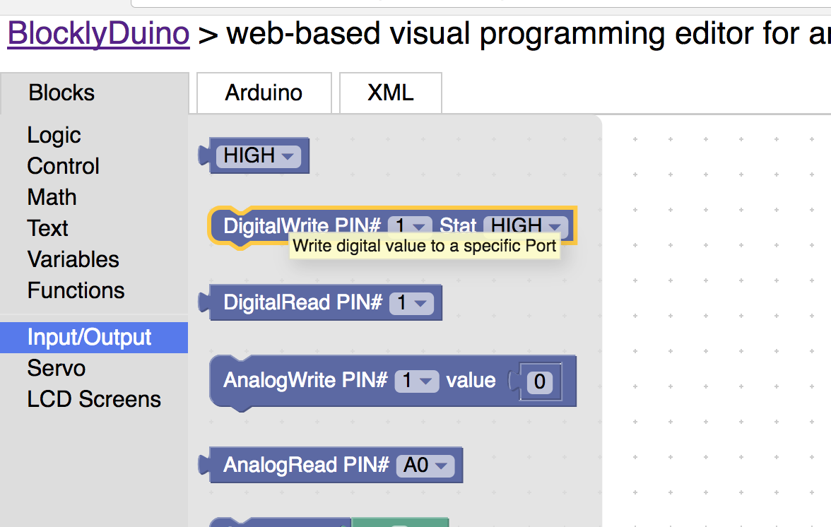
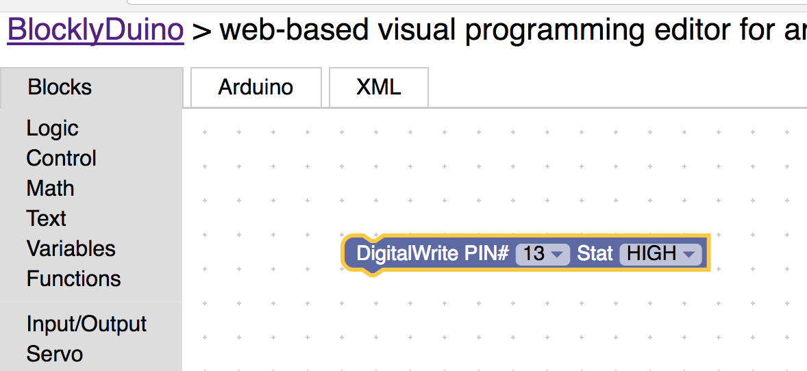
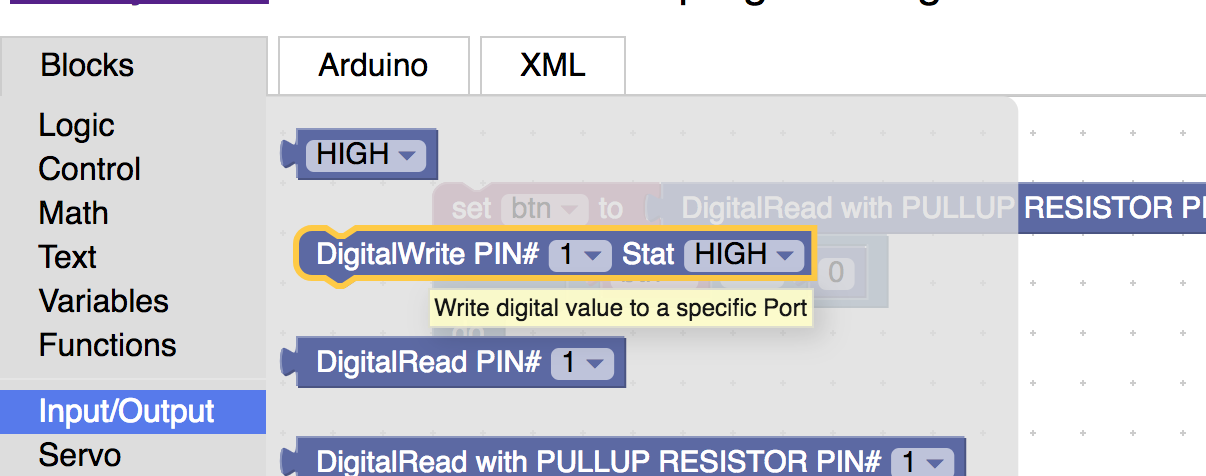
8) Click on Input/Output and drag the DigitalWrite block. Change the pin to 13 and make sure Stat is HIGH. High means that the electricity will be sent through that pin.
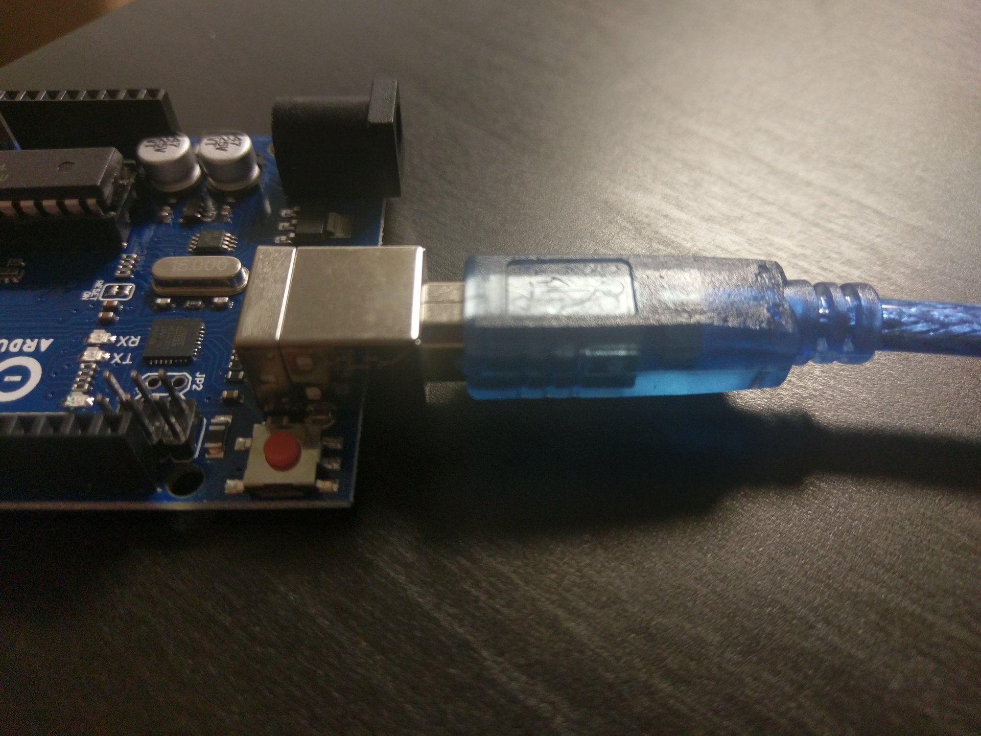
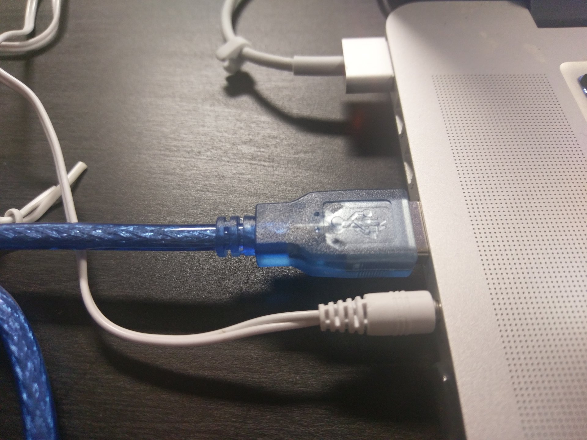
9) Plug the arduino into the computer.
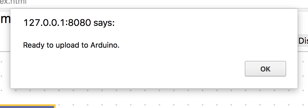
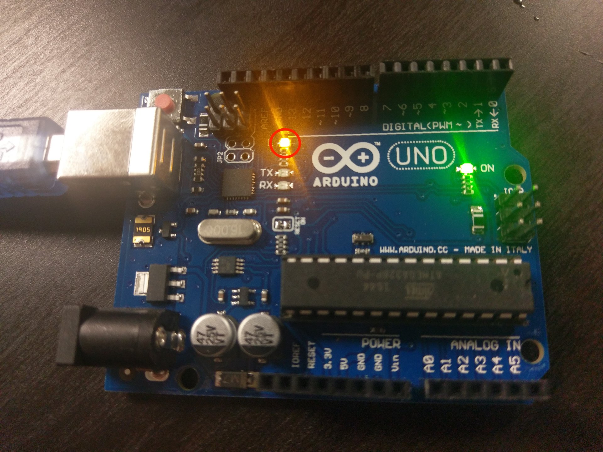
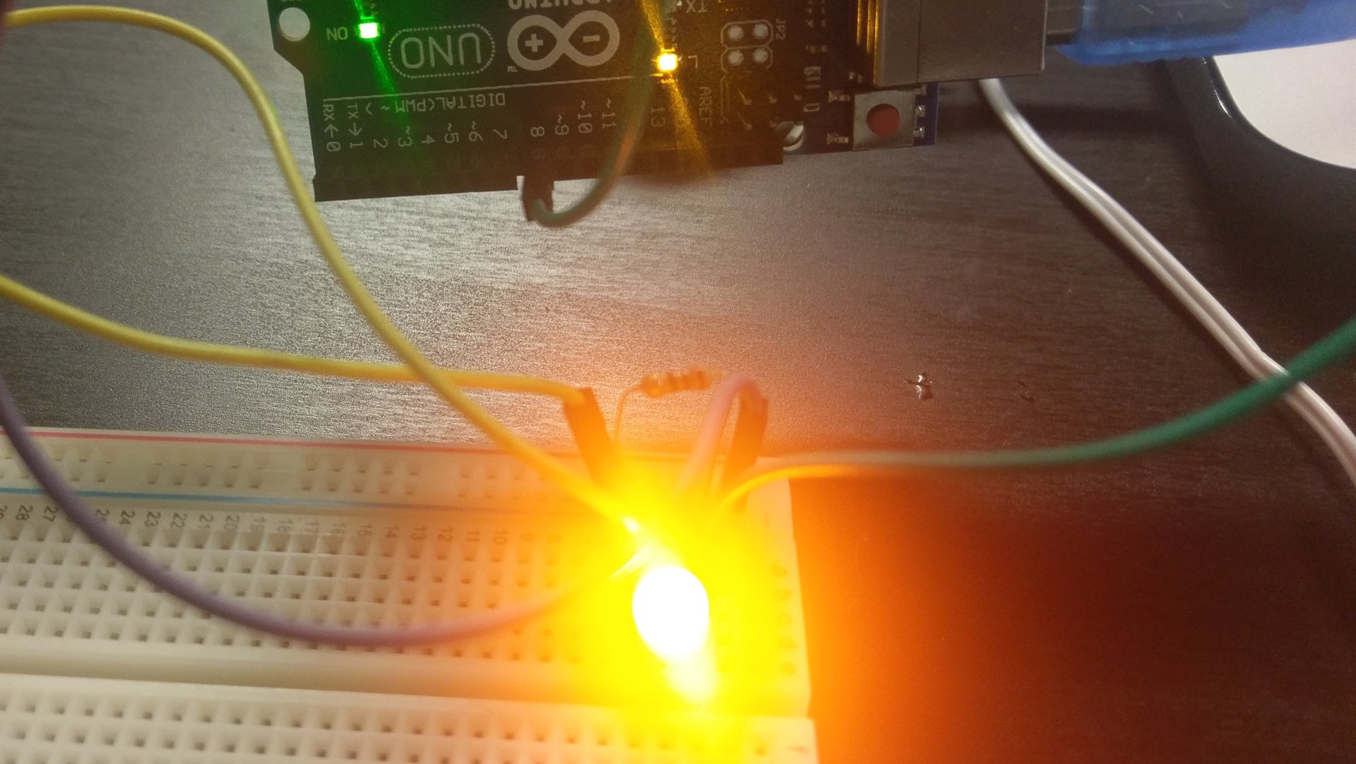
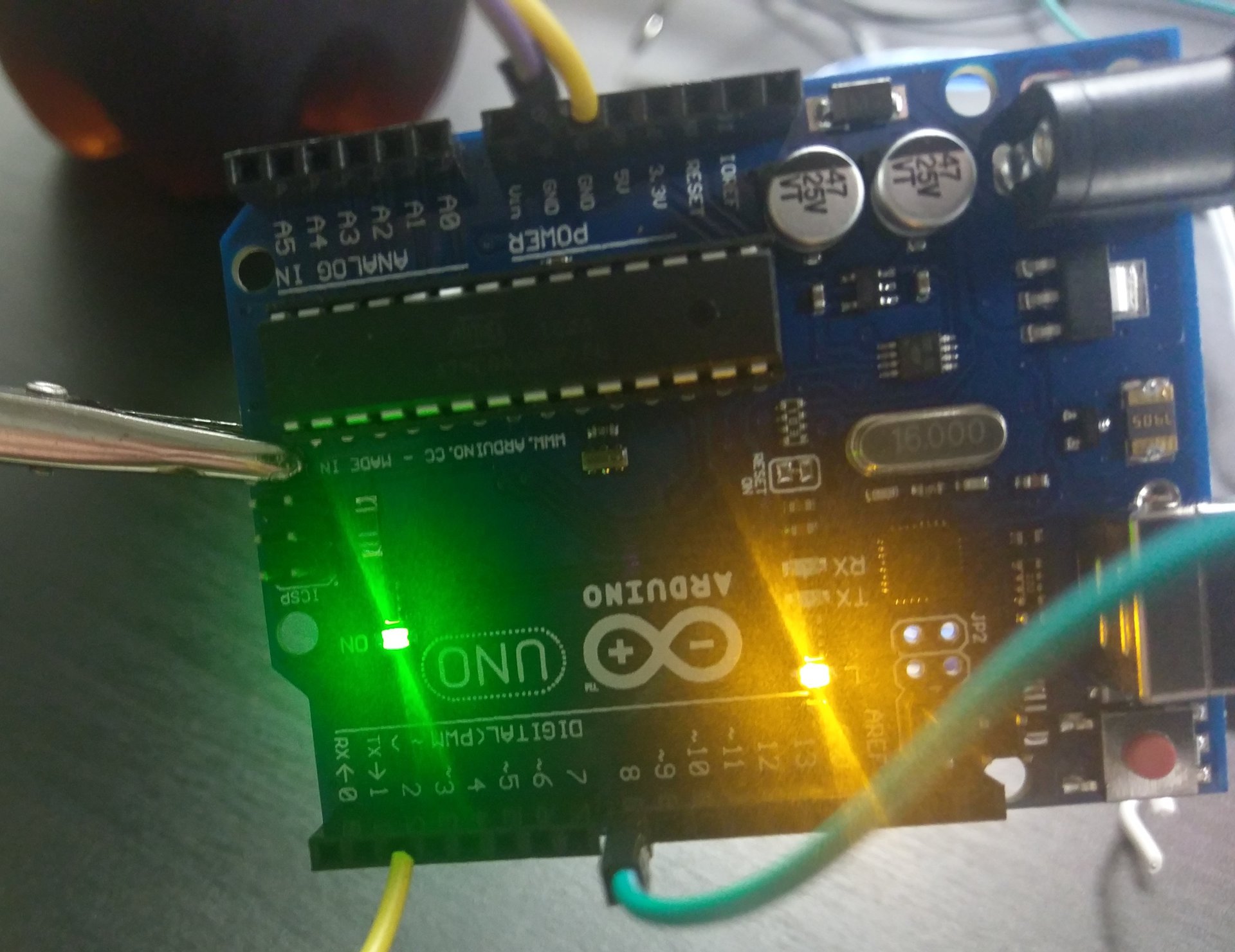
10) Click the upload button. This will upload program to the arduino. Once you are done you should see a yellow light. That yellow light is the arduino’s built in led. When you send electricity through pin 13 that led will light up.


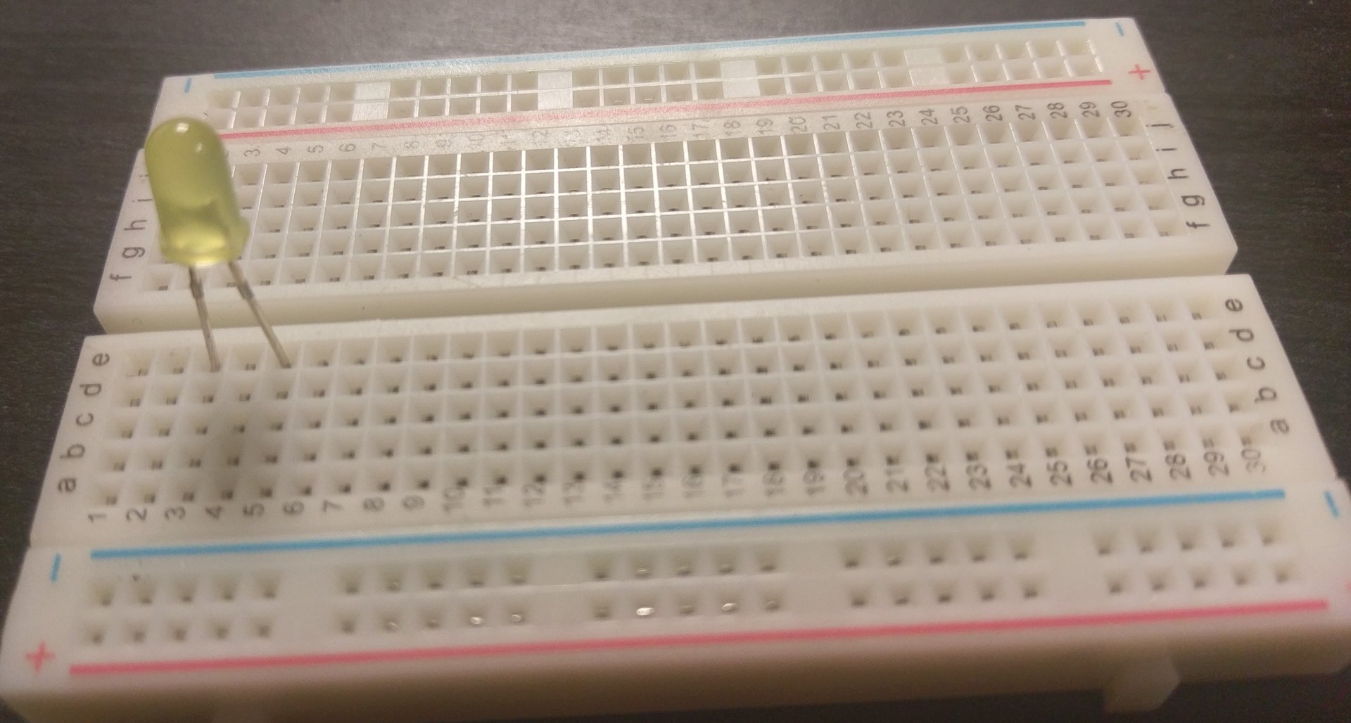
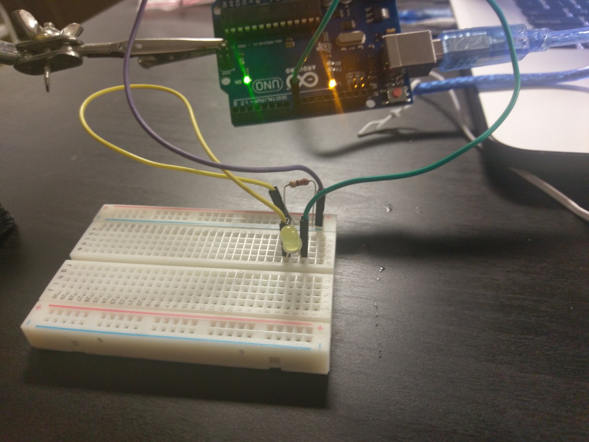
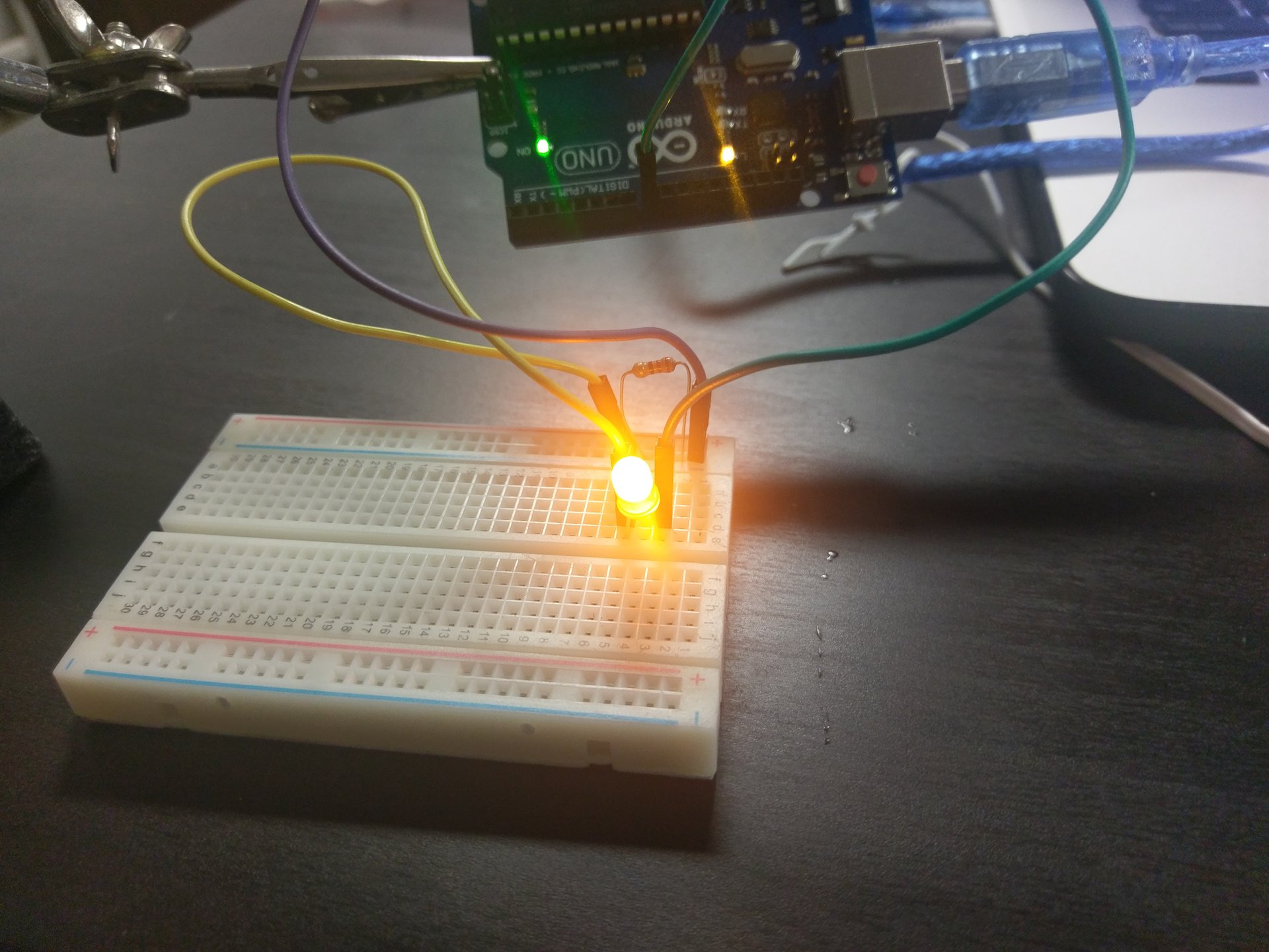
11) Take the led and plug the long end of the led and put into (3, e) of the breadboard and the short end into (5, e).
12) Take a male to male jumper wire and plug it into (5, d) and the blue line of the breadboard.
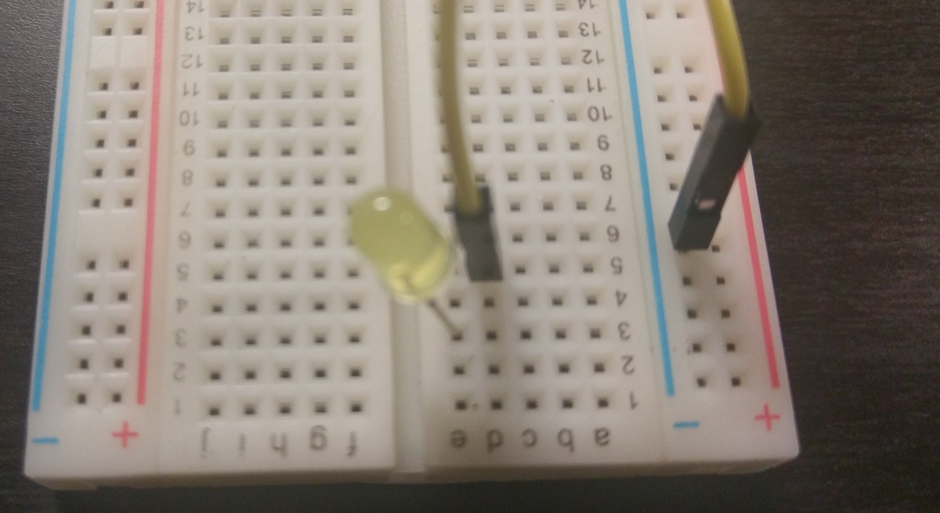
13) Take the resistor and plug it into the blue line, leave one space at the end.
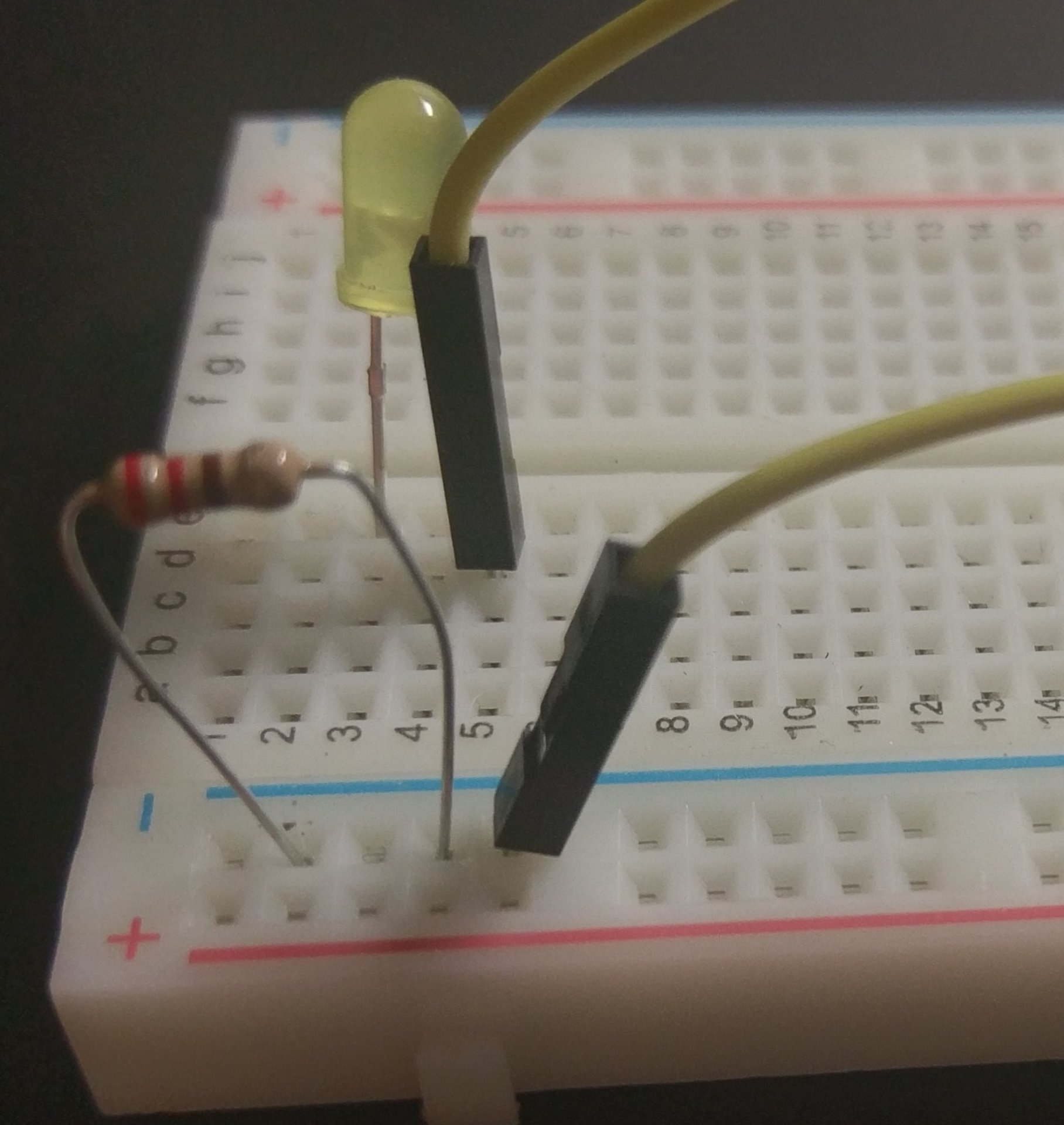
14) Take a male to male jumper wire and plug it into (gnd) ground of the arduino and the end space of the blue line on the breadboard.
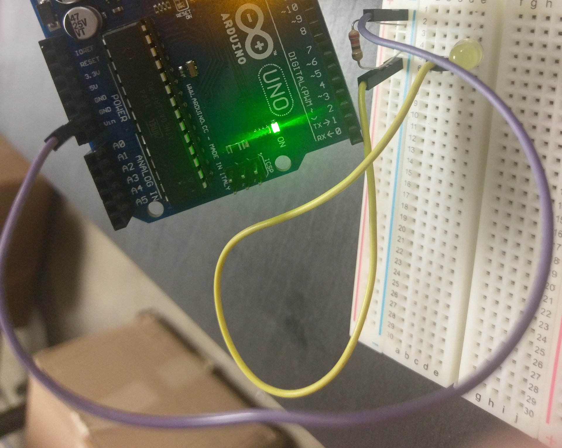
15) Take a male to male jumper wire and plug it into pin 7 of the arduino and (3, d) of the breadboard.
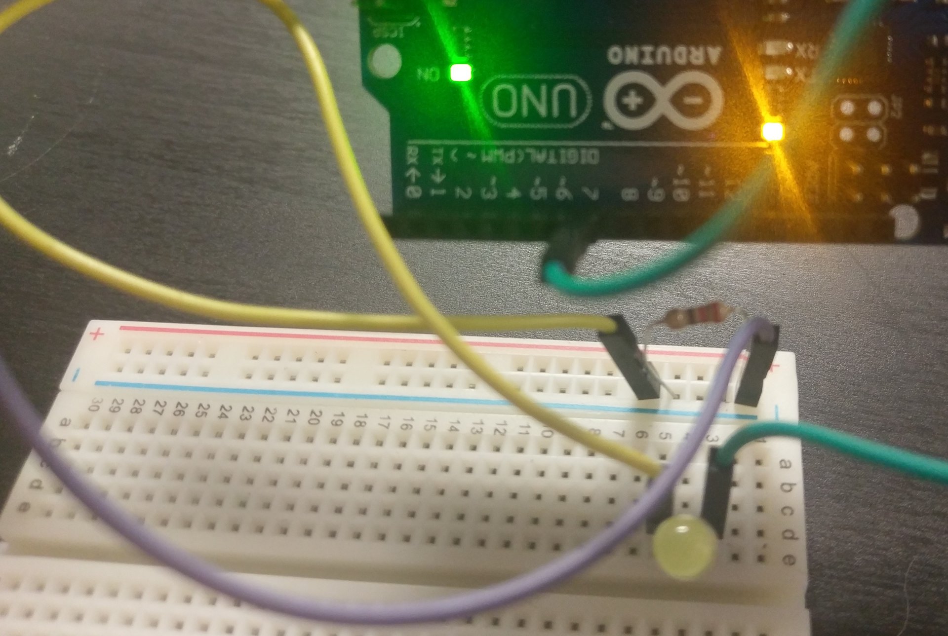
16) (Challenge) Can you change the program to make led light up by sending electricity to pin 7. To see your change click the upload button on the block web page. If you have trouble ask for help. :)
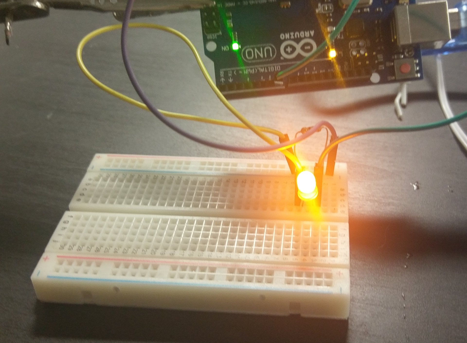
17) (Challenge) Move the wire to that is plugged into pin 7 to pin 8. Then change the blocks to make the led light up.
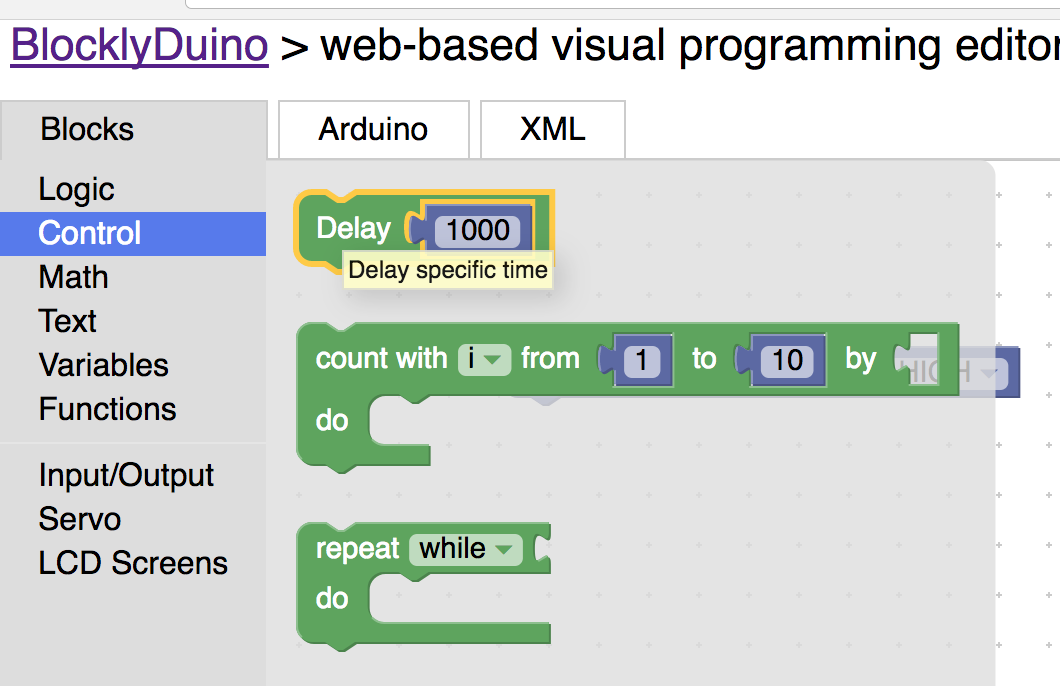
Now it’s time to make to Led blink. To do that we are going to learn a new block called delay. Delay pauses the program for period of time. The number you put in delay determines how many milliseconds the program will pause. A millisecond is 1/1000 of a second.
18) Open the control block and drag delay on screen. Then connect that block to the DigitalWrite Block.
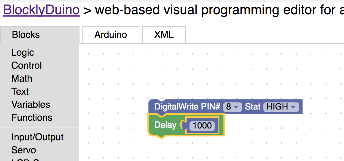
So the DigitalWrite Block takes 2 inputs, the pin number and (HIGH / LOW). If it is set to HIGH it will send electricity to the pin. If it is set to LOW it will not send electricity to the pin.
19) Drag the DigitalWrite Block on the screen and connect it to the delay block. Set it to LOW.
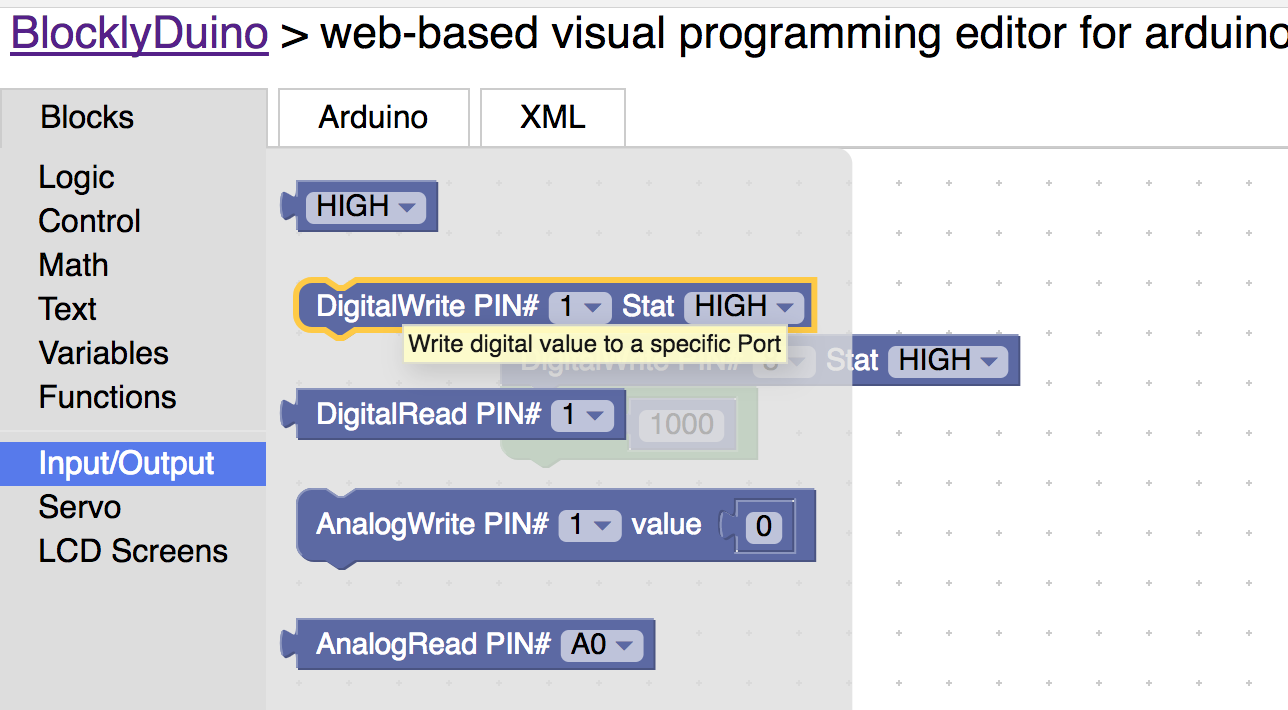
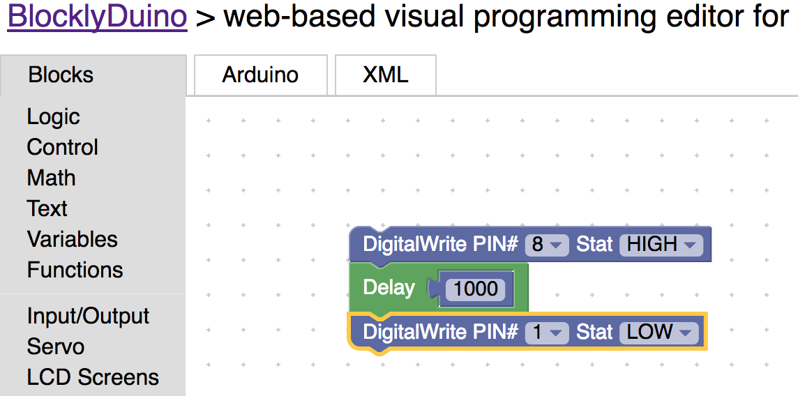
20) Now Drag another delay block onto screen and connect it to the block chain.
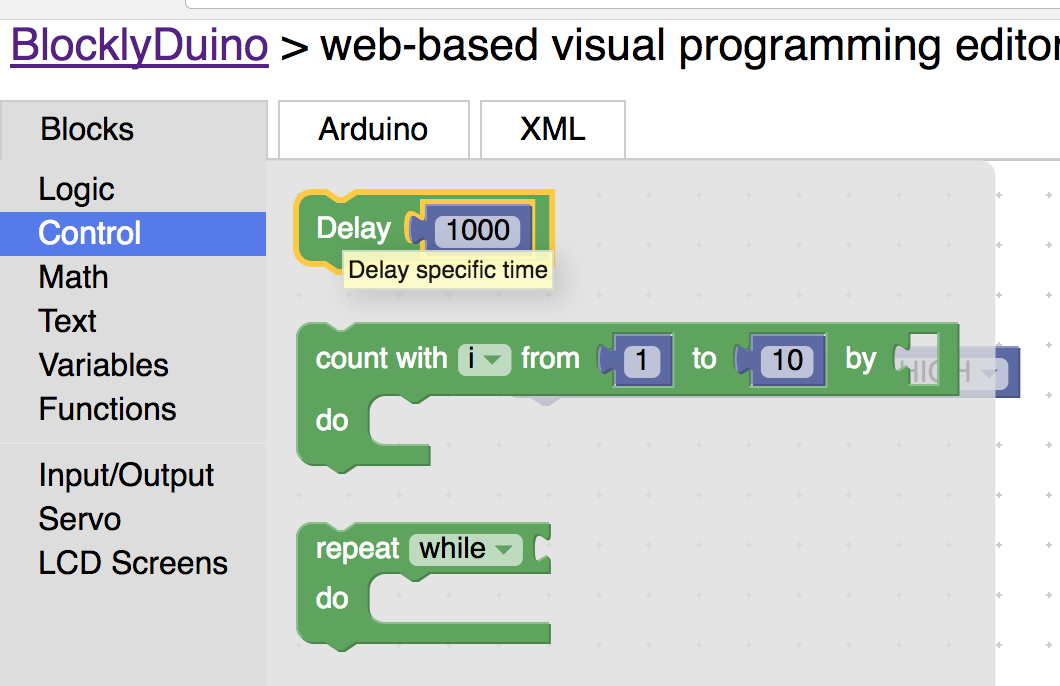
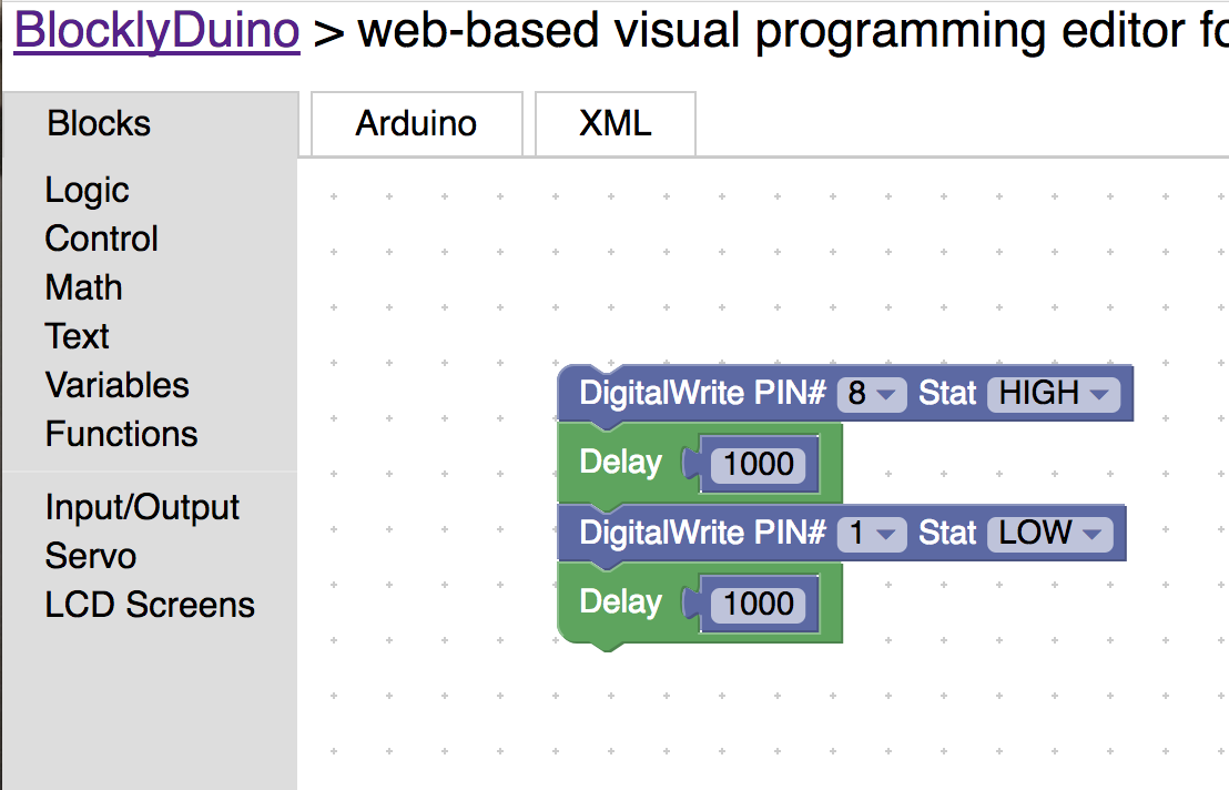
21) Now click the upload button.

22) (Challenge) Notice that led does not blink. Can you fix the blocks to make the led blink. What you are doing is called debugging. Debugging is fixing something that is wrong with a program. A bug is what is wrong with the code.
23) (Challenge) Can you make the led stay on for 2 seconds (2000 milliseconds).
Congrats!! You have just written your first complete arduino program. Go ahead and stand up and walk around for a minute.
24) Now we are going to delete all the code you have written. If you want to save it click on Save XML and store it some where you can find it later.


25) Now plug in the button. Plug ond wire into ground (gnd) and the other end into pin 2 of the arduino.

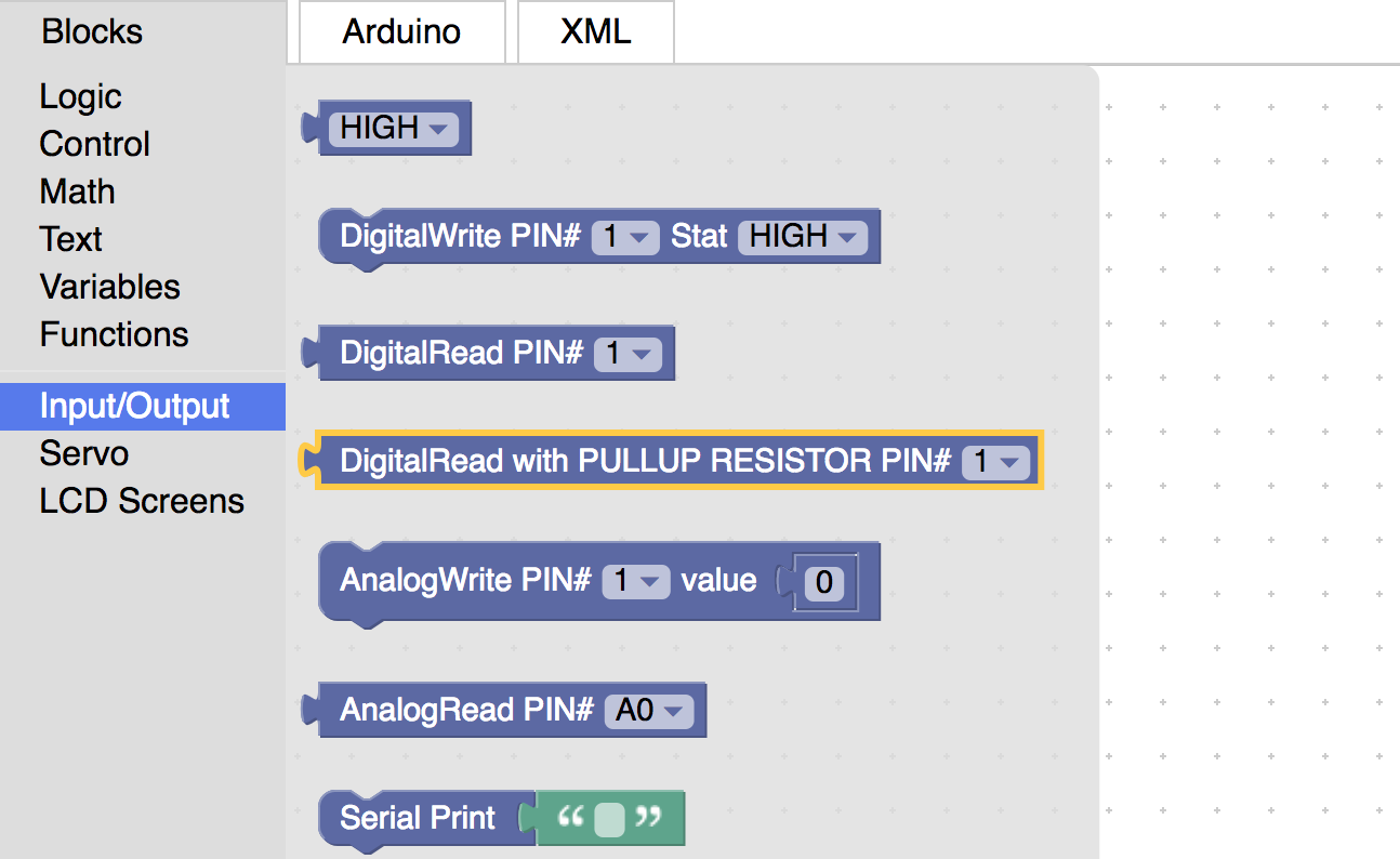
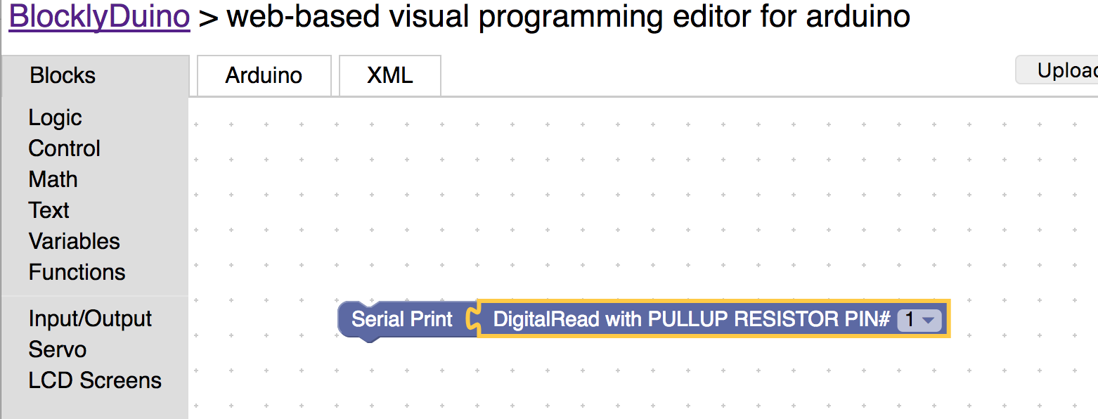
26) Now drag DigitalRead with PULLUP RESISTOR block to screen. Set the block to pin number 2.

27) Drag the Serial Print Block onto the screen. This block is used to send messages to your computer from the arduino.
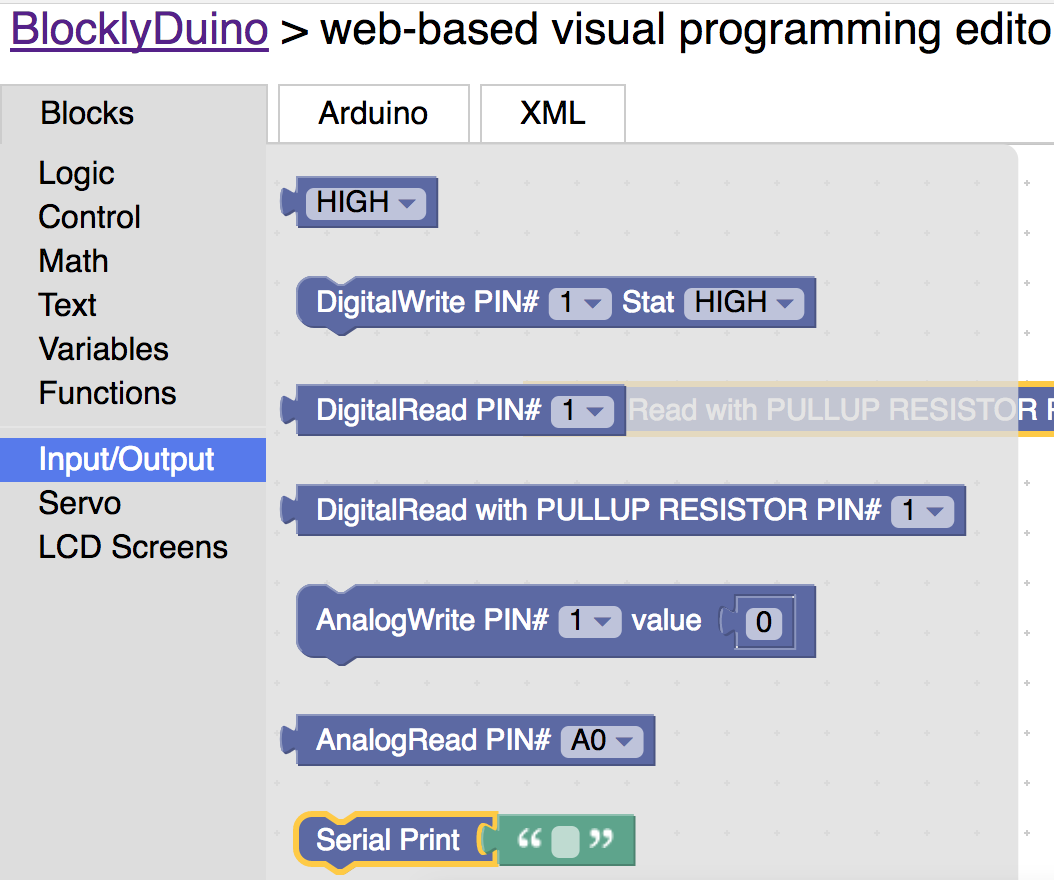
28) Connect the Serial Print Block to the Digital Read Block and throw away the green block with quotes.
29) Connect the delay block to the bottom of the serial block. Set the number in the delay block to 100. This means that arduino will pause for a 10th of a second.
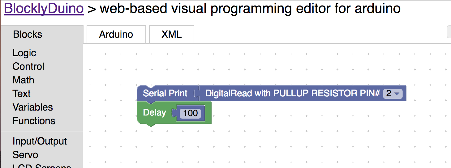
30) Upload the program to the arduino.

31) Click on logging / debgging to make the serial monitor appear.

32) Push the button and notice that when u push the button the output is 0 and that when u let go of the button it is 1.
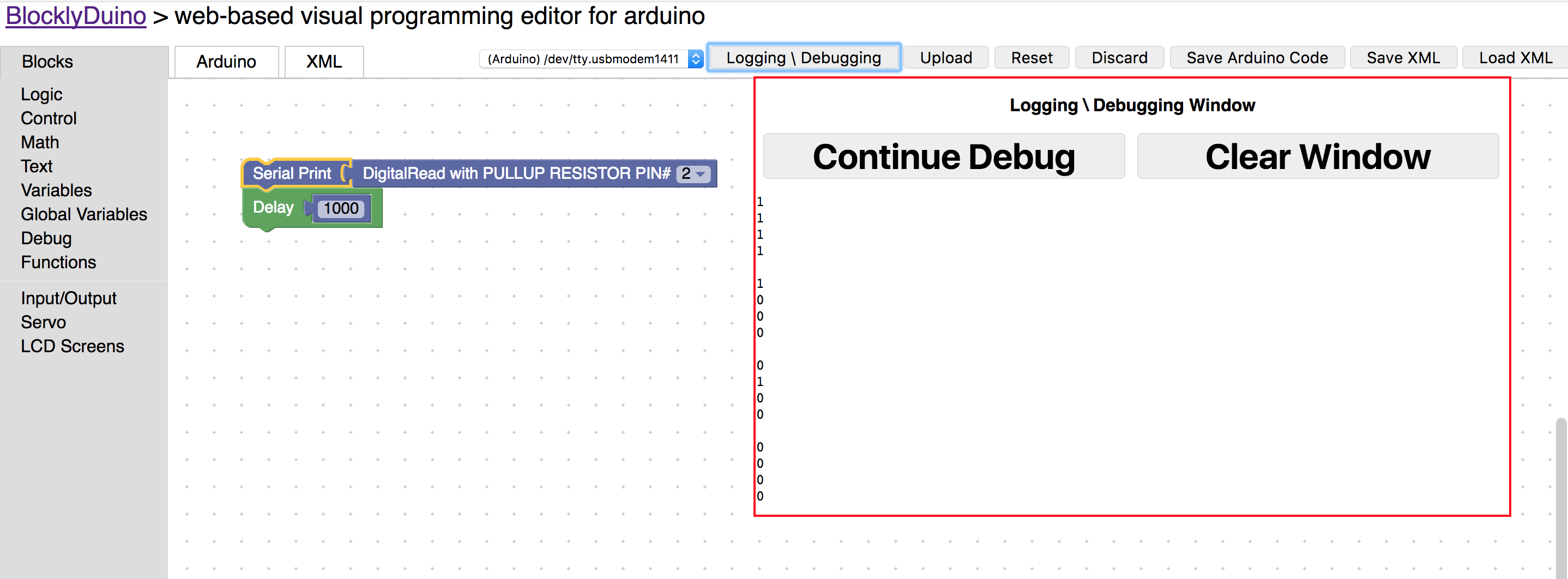
The Serial Block is a great way to help debug your code. :)
33) Now we are going to learn about variables. A variable is how we store data in the arduino. Go ahead and delete all the blocks and pull out variable block.
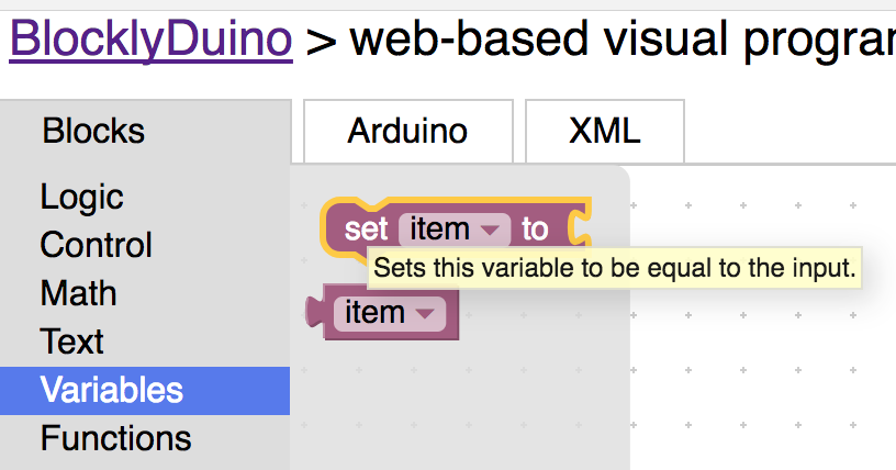
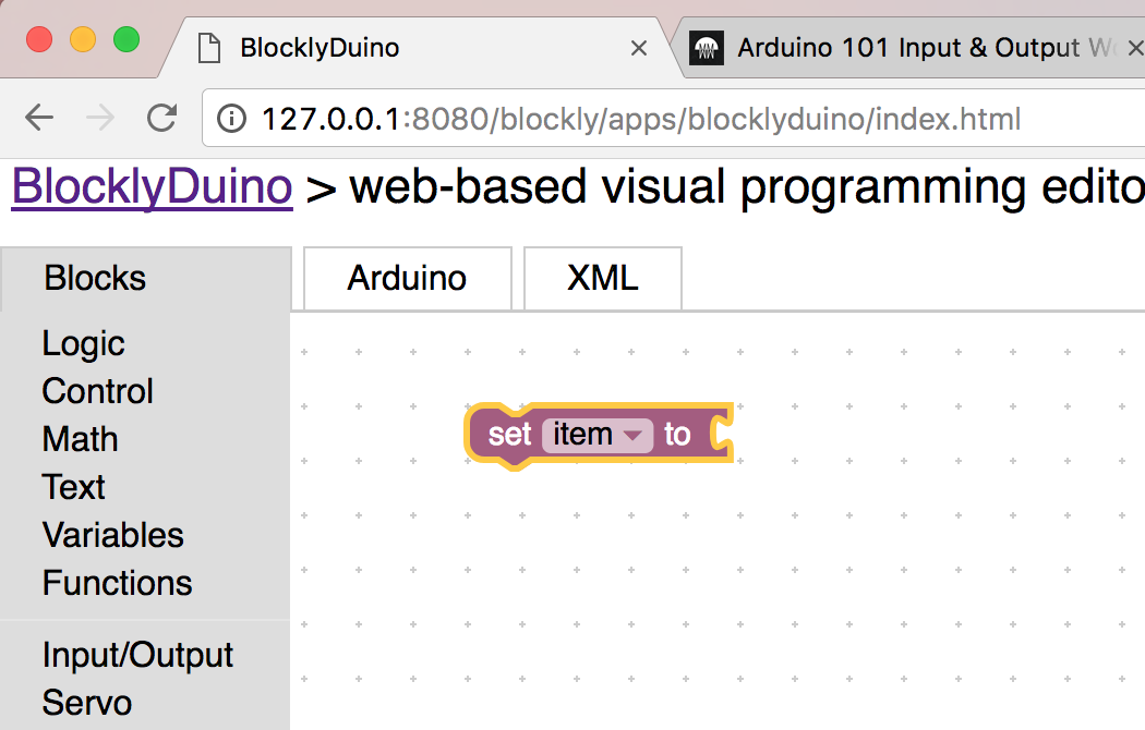
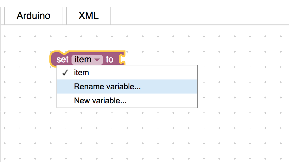
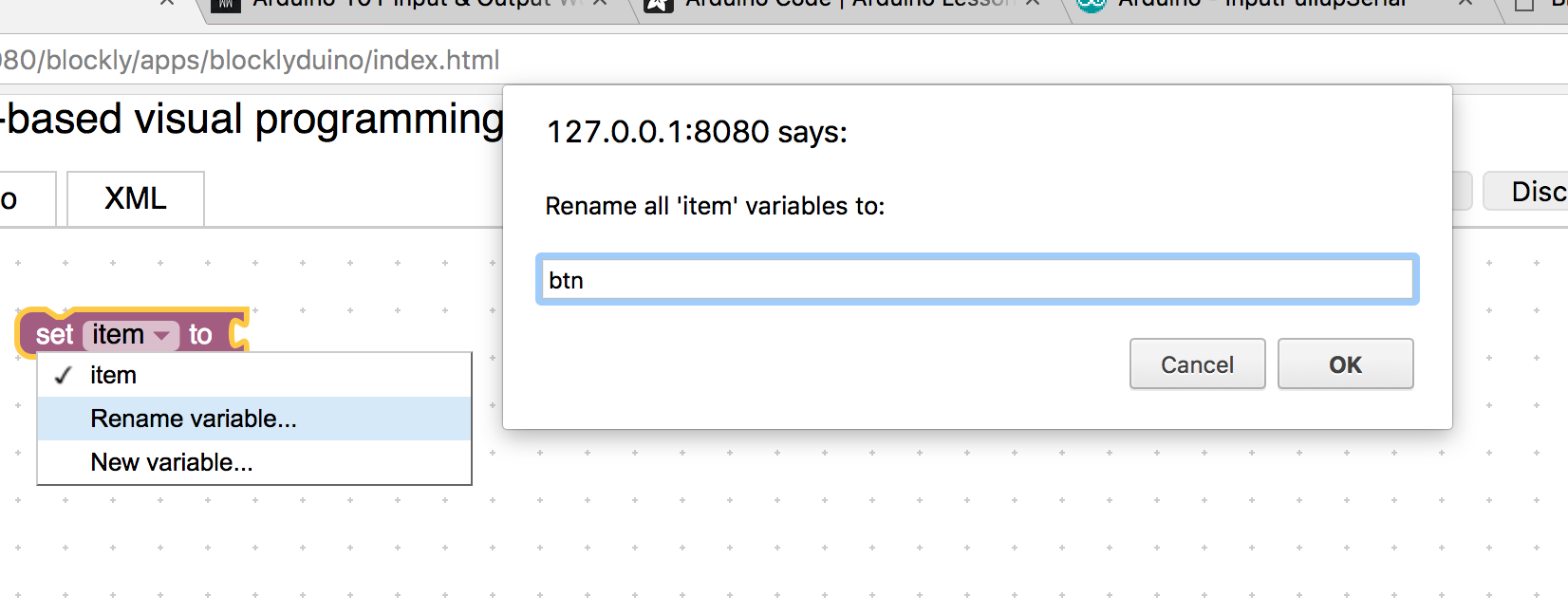
34) Now rename the variable to btn, for button. We will use this variable to store 0 or 1 for the button push.

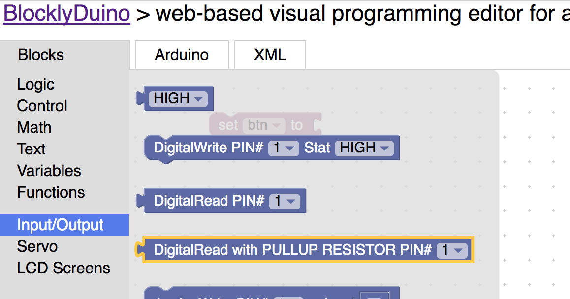
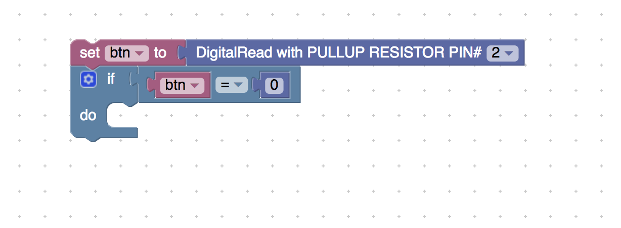
35) Now drag the DigitalRead Input PULLLUP Resistor Block and connect it to the btn variable block. Set the pin number to 2.

Now we are going to learn about if blocks. If blocks are used to make decisions in your program. If what is connected to the if block is true it will do all the blocks in the do space. Let’s build something to make this concept more clear.
36) Drag the If block and connect it to the bottom of the variable block.
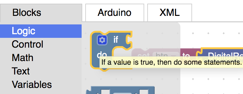
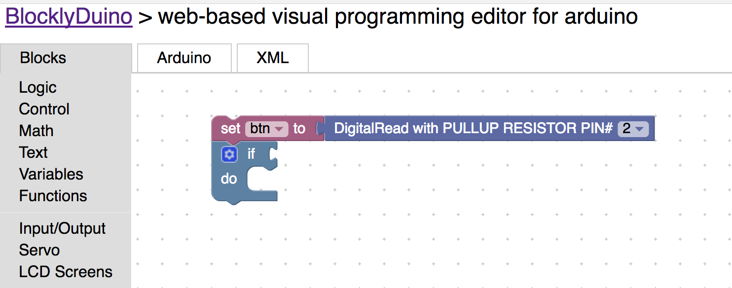
37) Now drag the compare block onto the screen and connect it to the if block. So if what is on the right and left side equal each other the arduino will run the blocks in the do space.
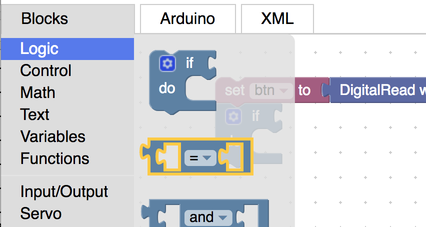
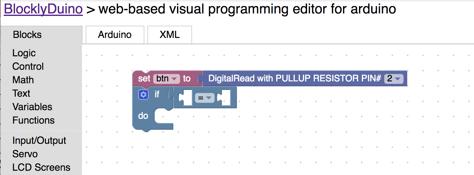
38) Go into the variable blocks and drag the btn block into the first part compare block. The btn block is variable that we created earlier.
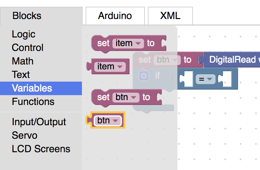

39) Now go to the math section and drag the number block the second part of the compare block.
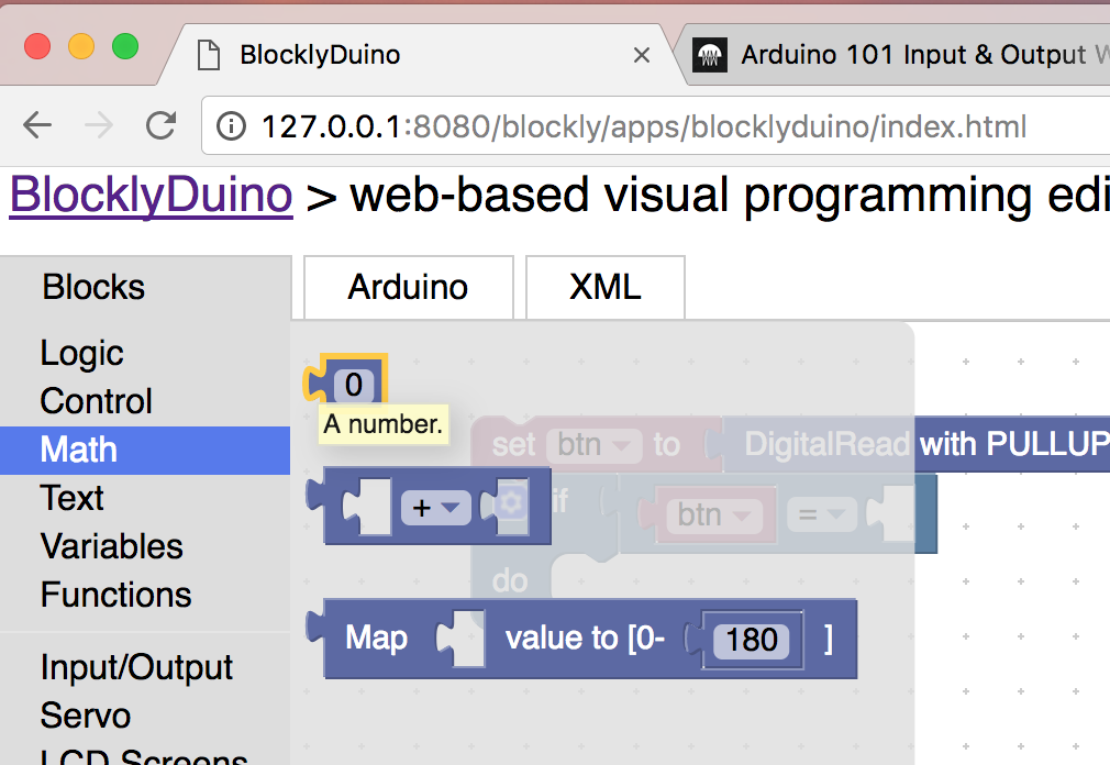
40) Drag Digital Write Block into the do space. Set the pin to 8.
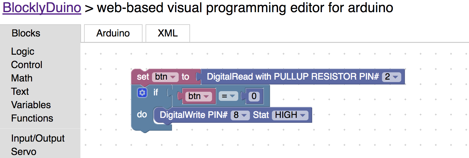
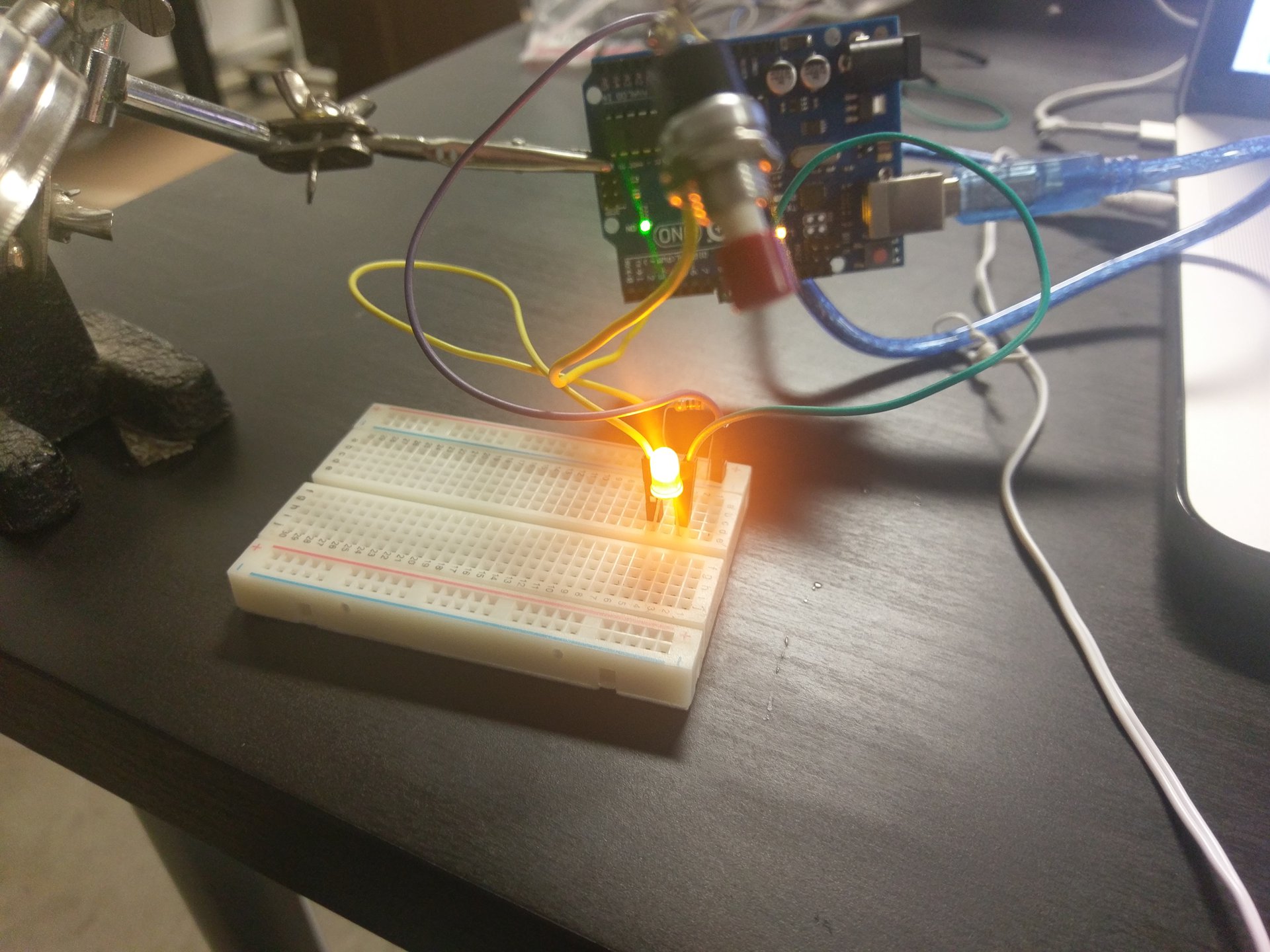
41) Upload program to the arduino and push the button. Notice that when u stopped pressing the button the light continues to stay on. Can you tell me why?

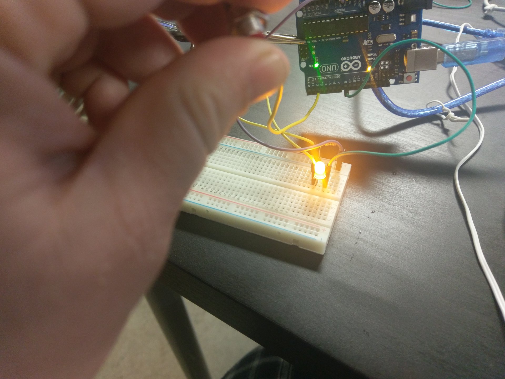
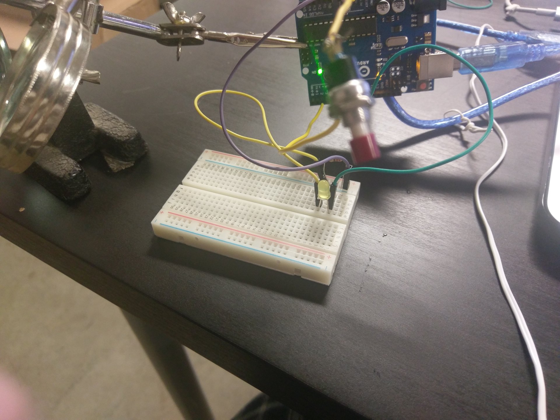
42) (Challenge) Can you create another IF block that will turn the led off when you stop pressing the button?
Challenge Projects
-
Make it so that when you push the button the led blinks 2 times.
-
Ask for a second led and wire set. Hook the other led to the side of the led in the breadboard. Make it so that when you push the button it makes the right led on and the left led off. And when you don’t push the button make it so that the opposite happens. You will want to hook the short side of the led to the blue end of the breadboard and the long side of the led to pin 4 of the arduino.
-
Just have fun and do what you want :)